
COLLABORATING INSTITUTIONS
Quantum research collaborators
Ewha Womans University
Professor Jusung Kim’s laboratory
Ewha Womans University
Professor Dae-Yun Kim’s laboratory
ETH Zurich · Switzerland
Professor Taekwang Jang’s laboratory
Korea Institute of Science and Technology (KIST)
Professor Dongyeon Kang
Joint research and co-supervision of graduate students through the KIST–SeoulTech cooperative graduate program.
SOURCE · PP. 135–140
Qubit platforms and the semiconductor opportunity
Quantum computing uses superposition, entanglement, and interference to manipulate quantum states. Its potential depends on the problem and algorithm, as well as on the quality of physical qubits and their supporting electronics.
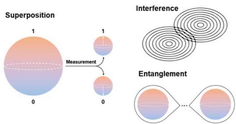
The chapter compares superconducting, trapped-ion, and photonic platforms. It also introduces semiconductor spin qubits, which encode information in electron spins within quantum dots.
| Platform | Strengths | Design challenges |
|---|---|---|
| Superconducting | Fast gates and a strong path toward lithographic integration. | Millikelvin cooling, noise sensitivity, and demanding control and error-correction requirements. |
| Trapped ion | Long coherence and high-fidelity control and entanglement. | Laser control, vacuum infrastructure, gate speed, and system scaling. |
| Photonic | Optical interconnect compatibility and opportunities for chip-scale integration. | Photon loss and the difficulty of implementing interactions between qubits. |
The roadmap describes an international ecosystem combining quantum processors, cloud access, simulation software, and classical computing. Its Korean overview emphasizes quantum simulators, photonic integration, and evaluation infrastructure. Across these approaches, device development and system integration must advance together.
SOURCE · PP. 140–142
Superconducting qubit circuits
Josephson junctions provide the nonlinear element in superconducting qubits. Circuit choices trade off noise sensitivity, coherence, control complexity, and fabrication requirements.
| Circuit | Main feature | Tradeoff |
|---|---|---|
| Charge qubit | A Cooper-pair box formed by a Josephson junction and capacitance. | Fast electrical control, with sensitivity to charge noise and crosstalk. |
| Flux qubit | Josephson junctions in a superconducting loop. | Useful anharmonicity, with flux-noise and control/fabrication challenges. |
| Transmon | A Josephson junction with a large shunt capacitance. | Reduced charge-noise sensitivity and scalable control, with relatively low anharmonicity. |
| Fluxonium | A Josephson junction combined with capacitance and a large superinductance. | Long coherence and strong anharmonicity, with more demanding fabrication and control. |
SOURCE · PP. 142–144
Microwave control and multi-qubit scaling
Microwave pulses rotate a qubit state on the Bloch sphere. Pulse amplitude, phase, frequency, and envelope shape determine the intended operation. Digital waveform generation is connected to the qubit through DACs, filtering, and, where required, mixers and local oscillators.
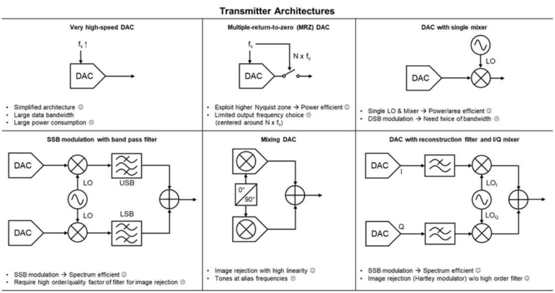
| Architecture | Benefit | Constraint |
|---|---|---|
| Direct high-speed DAC | A relatively simple route to wideband signal generation. | High sampling rates and power consumption. |
| Multi-return-to-zero DAC | Uses higher Nyquist bands to lower the required sampling rate. | Unwanted spectral components and a restricted choice of output bands. |
| Mixer-based upconversion | Translates lower-frequency DAC signals into the qubit band. | Local-oscillator distribution, sideband selection, and filtering. |
| I/Q and mixing-DAC approaches | Support single-sideband generation and image rejection. | Linearity, alias tones, and reconstruction-filter requirements. |
Sharing control hardware
Scaling requires simultaneous operation with controlled crosstalk and sufficient spectral separation.
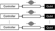
Space division
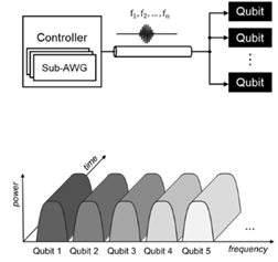
Frequency division
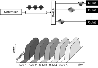
Time division
| Method | How it scales | Main tradeoff |
|---|---|---|
| Space division | A separate drive line for each qubit. | Straightforward control, but rapidly increasing wiring and interconnect complexity. |
| Frequency division | Several qubit frequencies share one drive line. | Parallel control with fewer cables, but greater spectral and pulse-shaping demands. |
| Time division | Control resources are reused across different time slots. | Lower hardware cost, with additional scheduling and execution time. |
SOURCE · PP. 145, 149–150
Bringing electronics closer to the qubits
Room-temperature instruments are convenient, but long connections into a cryostat introduce wiring complexity, signal distortion, and thermal-noise challenges. Cryo-CMOS places selected control and readout functions closer to the quantum processor.
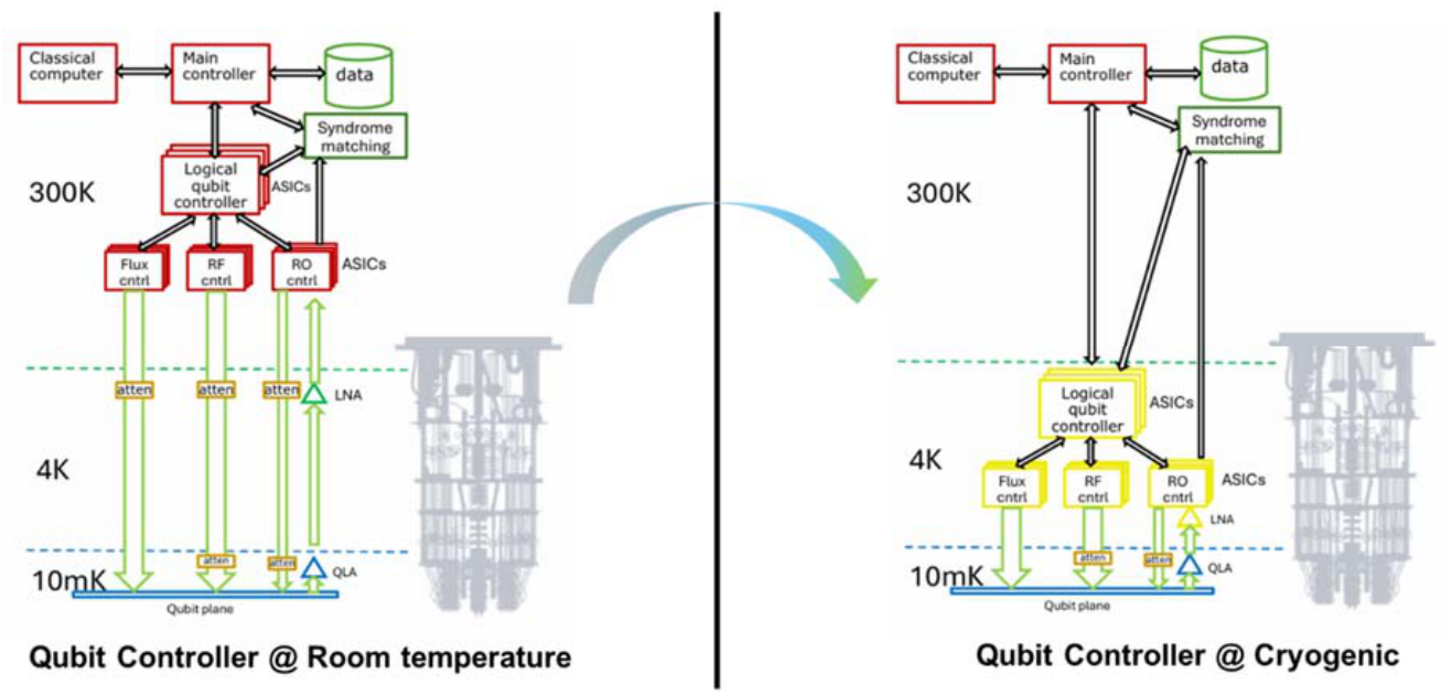
The temperature stages remain distinct: the chapter describes superconducting qubits at approximately 10–20 mK, while the integrated interface circuits in its comparison operate at about 3–4 K. The available cooling power makes low energy consumption a central design constraint.
- Reduce cable count through integration and multiplexing.
- Maintain waveform accuracy, linearity, and low added noise.
- Balance circuit power against the cryostat’s thermal budget.
- Co-design interfaces and interconnects for larger qubit arrays.
SOURCE · PP. 146–150
From a reflected signal to a qubit decision
Dispersive readout detects how a coupled resonator responds to a probe signal. The qubit state shifts the resonator response, changing the phase and amplitude of the returned microwave signal. The receiver extracts this information and classifies the state.
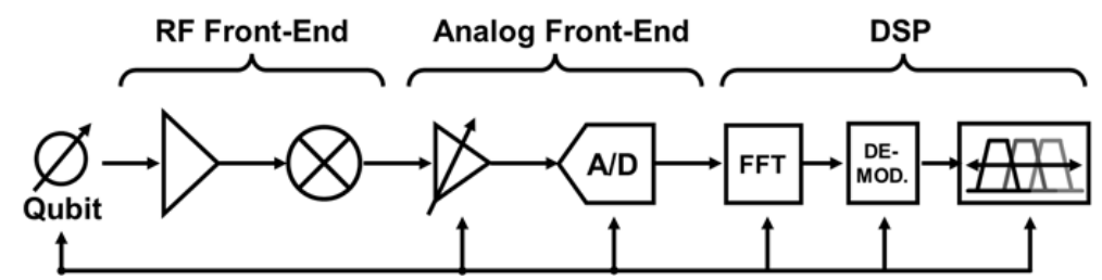
- Parametric amplifier
A JPA or TWPA provides near-quantum-limited amplification.
- Low-noise amplifier
Adds gain while limiting further degradation of SNR.
- Frequency conversion
A mixer translates the signal to IF or baseband.
- Digitization
An ADC captures the signal when digital processing is used.
- Demodulation & decision
I/Q extraction, filtering, and discrimination reveal the qubit state.
I/Q demodulation can be implemented before digitization or within the digital signal-processing chain. Frequency-division multiplexing enables several resonators to share a readout path.
Emerging readout approaches
The chapter highlights thermal-detector readout and analog homodyne Cryo-CMOS as alternatives to conventional receiver chains. The 2024 bolometer study reports 62% single-shot readout fidelity; 99% is discussed as a design target supported by analysis. The 2025 homodyne work explores readout without the conventional ADC/DSP processing chain, targeting lower power and shorter processing paths.
Selected circuit results in the chapter
| Metric | Reported examples |
|---|---|
| CMOS technology | 22 nm FinFET and 28–40 nm bulk CMOS. |
| Circuit temperature | Approximately 3–4 K. |
| Controller spectral purity | Several implementations report SFDR above 40 dB. |
| Readout accuracy | One homodyne example reports 93% circuit-only fidelity. |
| Power | Millwatt-scale implementations, with different per-qubit, per-channel, and waveform-dependent reporting conventions. |
These are results from different circuits and measurement conditions. Circuit-only readout fidelity is distinct from qubit gate fidelity or complete-system readout performance.
SOURCE · PP. 150–151
A path toward integrated quantum systems
The 2026 edition presents the following development outlook. These periods and qubit counts are roadmap projections, rather than a record of milestones already achieved.
| Period | Roadmap outlook | Supporting technologies |
|---|---|---|
| 2026–2028 | Modular architectures targeting thousands of qubits. | High-fidelity chip-to-chip coupling, automated quantum error correction, and coordinated control. |
| 2029–2031 | Fault-tolerant systems targeting about 200 logical qubits. | Quantum instruction sets, cloud scheduling, and reliable system operation. |
| 2032–2035 | Systems targeting 1,000 or more logical qubits. | Quantum–classical software integration and application-level progress in chemistry, materials, and optimization. |
| 2036–2040 | Quantum-centric computing at much larger scale. | Cryogenic chiplets, quantum SoCs, and integration with HPC, AI infrastructure, and data centers. |
Circuit-design priorities
The chapter’s central direction is to improve integration, power efficiency, and reliability together. Scalable quantum computing requires progress in qubit devices, Cryo-CMOS controllers, low-noise readout, error-correction support, and system interconnects.
SOURCE · PP. 152–153
Source and selected references
This page condenses Chapter 10, “Quantum Computing Semiconductor Technology,” from the source roadmap. The chapter’s bibliography appears on pp. 152–153.
View the complete chapter bibliography (opens in a new tab)- [3]
J. P. G. van Dijk et al. — DDS-based SoC design for high-fidelity multi-qubit control. IEEE TCAS-I, 2020.
- [4]
B. Sadhu et al. — Cryogenic CMOS circuit challenges and solutions for scaled quantum computing. IEEE CICC, 2025.
- [6]
A. M. Gunyhó et al. — Single-shot superconducting-qubit readout using a thermal detector. Nature Electronics, 2024.
- [7]
D. Minn et al. — A 40 nm Cryo-CMOS homodyne-demodulation readout SoC. IEEE TCAS-I, 2025.
- [8]
J. P. G. van Dijk et al. — Scalable, frequency-multiplexed Cryo-CMOS control of spin qubits and transmons. IEEE JSSC, 2020.
- [11]
K. Kang et al. — A 40 nm Cryo-CMOS controller with DRAG generation for superconducting quantum computing. IEEE JSSC, 2025.